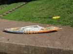
Building my own kayak (5) – First float
After the cockpit-rim has cured I couldn’t wait to get out onto the water for a first float. However, there was a problem to solve first: the hose that I have used as cockpit-rim plug has moved overnight in the front area of the cockpit-rim, so this part was messed up and required a fix. I needed to remove some of the cured composite in this area and after that I have repaired the front part of the cockpit-rim temporarily by using epoxy putty. By using an infrared light as heat source I accelerated the curing process so I was able get the boat on the water today:


In summary, apart from the faulty front part of the cockpit-rim I was impressed that the simple approach of using a hose as plug for the cockpit-rim works quite well. Initially I had planned to create a three part mould which includes the cockpit-rim. Fortunately Jim had made clear that this is not the best idea and he advised to use a hose instead. I’m really lucky that I don’t have to reinvent the wheel and other people are sharing their own experiences with me.
Here you can see the deck and hull attached to each other by loads of tape (the prototype just needed to be functional so there was no need to look beautiful, the first real boat will look better, I promise):

My first impressions are quite positive: even with the foot bumps placed 5cm too close to the cockpit I have plenty of leg and foot room whilst having a decent chop. I guess I will be able to remove even more volume without sacrificing comfort. So, regarding this point my boat beats my Shred and my Funk.
Assessing the performance of the boat is difficult as the prototype is not stiff enough and I have neither used a seat nor any fitting at all. Additionally, the prototype leaks quite a lot so I only had a few minutes during each run after I needed to remove the water. Given those handicaps I must say that I liked the performance a lot, as getting the boat vertical was quite easy.
I decided that there are two things to fix for the next iteration: as mentioned in my last post, the foot bumps will be moved 5cm to the front. Secondly, I will make the stern part of the boat a little bit more slicy by changing the round sidewalls to a more triangular shape.
Here you can see a quick video edit of today’s session:
I believe that most of the instability you can see is due to the lack of fitting, as I was just moving around inside the boat. Also, I cannot deny that I need to work on my technique – but that’s another story…
Building my own kayak (4) – Prototype lay-up and cockpit-rim
Instead of kayak building I was on the road for some actual kayaking, so there was no update on this blog for nearly a month.
As intended, I have started building a simple prototype directly from the plug. With that I want to make sure that I will fit in the boat comfortably and that it behaves as I want it to.
I layed-up the hull first, as it seemed simpler because it does not have as many details as the deck has. I have applied 4 layers of 160 g/sqm glass and the resulting hull was way too flexible. So, after curing, I added a single layer of non-woven polyester fabric (150 g/sqm), which contributed to additional 3 mm thickness of the hull. The processing of the polyester was a real pain in the ass. It really sucked… a lot of resin – I needed around 3 kg to fully saturate the polyester. So I had to prepare new resin for 4 or 5 times. Furthermore, it was quite difficult to saturate the fabric as gravity always moved the resin from the vertical sidewalls to the bottom. My original idea was to use this cheap fabric for building the mold, too. However, whilst the fabric itself is cheap, the final product is probably more expensive than using proper glass fabric as so much resin is required… I will just keep the remaining 10 sqm of non-woven polyester for absorption if, one day, I will go one step ahead and layup-up using vacuum bagging.
Here you can see the hull lay-up with the glass only:

The final hull including the polyester ended up to be quite heavy and it still seems a bit brittle. However, for my needs it should be sufficient.
For the deck I decided not to use the polyester again. Instead, I have layed-up 4 layers of the same glass like I did for the deck. Additionally, I have put in various pieces of the glass fabric rests between these layers. With a lot of curvature and the additional layers of glass the resulting deck was less flexible than the initial hull.
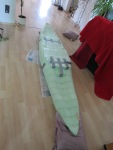
For both, deck and hull, I have used plastic wrap (fixed with double-sided adhesive tape) as separation between my plug and the lay-up:


After a quick and dirty hull and deck join using duct tape I did a first sitting-in-the-boat test. I have noticed that I need to move my foot bumps around 5cm to the front – however, for a final decision about that I need to find out the optimal seating position so that the boat is balanced, first.
-

- deck and hull separately
-

- deck and hull joined
-

- deck and hull fixed with duct tape
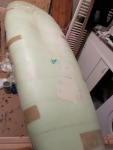
While I am writing this, the cockpit-rim is curing so that I am able to get the boat on the water for a first float. Here you can see a few pictures of the cockpit-rim:
-

- scraps of glass fabric for the cockpit-rim lay-up
-

- 16mm tube is used for the cockpit-rim
-

- cockpit-rim layed-up. After a partial cure I will cut off the fringes with a utility knife
I have noticed a twist in my plug that becomes even stronger towards the stern. Instead of starting with surface finish work this needed to be fixed first. In order to compensate the twist I had to remove about 2cm of foam (which has already been covered with glass and epoxy) at the right-hand side of the stern hull, and I had to add these 2cm at the left-hand side of the stern deck. I used an orbital sander for grinding off material and initially I have used polyester putty for the extension (only on top of the glass because the solvent contained in polyester resin eats styrodur). Due to its price and the complicated processing (hardens within 5-10 minutes), I have swapped to using plaster. I got a 5kg bag of plaster powder in a hardware store for less than 10 EUR, which just needed to be blended with water. The processing is very simple as one can almost arbitrarily refine the shape of the applied plaster. Up to now there are two shortcomings: my foam plug is now quite heavy – I guess I have added about 5kg. Also, the hardening process of the plaster takes ages due to its thickness (it is drying for three days now, and the thick spots are still wet). Also, I am a bit worried that the plug becomes brittle and might finally break, retrospectively I should have attached some small stripes of the original foam first, and then just do refinement using the plaster…
For recognising at what places to compensate for the twist and other major irregularities a water bubble and viewing from orthogonal angles (to the boat’s main axes) were the most important ingredients. Apart from some minor-ish surface irregularities I guess I have a somewhat smooth and symmetric boat. I expect to be able to fix these later on using thinned polyester putty. Up to now this has taken me around 14 hours – there is still some sanding to do after the plaster has completely dried.
Next, I will create a prototype directly from the foam plug. I will do this for mainly two reasons: Firstly, I am quite unsure whether I will actually fit in the boat and secondly, being my first boat to be built I have no clue whether the shape will actually work. So the plan is to roughly evaluate the current shape, do changes accordingly, finish the surface and then create a mould. For creating a prototype as cheap as possible I will just use some plastic wrap sticked to the plug using double-sided adhesive tape as separation between the plug and the glass work. I have in mind to use only 3 or 4 layers of 160g/sqm glass – there is no need to last more than one or two flat water sessions. If that’s not stiff enough I can still add some more layers after the first layers have cured.
Before writing about the current progress I like to complement my previous post with these images about the individual foam slices and a partial foam plug:


After I have glued all foam slices together I did a lot of sanding in order to even out minor irregularities of the foam slices, for shaping the bow and stern, making the plug as symmetric as possible, adding the recesses for the hands behind the cockpit rim for simpler getting out of the boat and for shaping the cockpit rim. Sanding the foam was more difficult than I expected – I ended up with lots of little holes and regions with a rough surface due to applying to much pressure when sanding. Also, I noticed that the foam has a preferred direction for sanding (note to myself: next time cut out all slices in the same orientation from the big foam sheets), resulting in scratches at the transition between two slices. For sanding, I used sanding paper from grit 60 to 120, mounted with double-sided tape onto small pieces of styrodur foam with different shapes (planar, convex, concave, or a particular shape that was used to go around the cockpit rim) . In order to fill the holes and scratches I have applied putty. I found the water-based stuff that is used to fix minor cracks in walls to be perfect for this: it does not smell, it is cheap, it is easy to sand and it does not interfere with epoxy. All in all the sanding and filling of the foam plug took me 20 hours.
-

- at the edge you can still see some uneven spots
-

- here the spots are more even
-

- the cockpit rim has required a lot of putty and even more sanding. the silver tape has been used for fixing some foam rubber in order to get a more smooth surface along the cockpit rim

-

- recess for the left hand while getting out of the boat
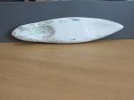
After that was finished I have applied two layers of 160g/sqm glass on the hull and the deck. After glassing the hull I have wrapped plastic foil around the entire boat, resulting, in theory, in a smooth surface. In practice, some wrinkles had formed due to the plastic wrap, which can be sanded down anyway. A rather big problem was that a large bubble at the concave spot between the legs (see pictures of 3d model in previous post) has remained unnoticed until I unwrapped the foil. As the resin had already cured at this point I needed to cut out the glass in this area and redo it.
The deck was even more problematic: I decided not to use foil again as the deck had multiple concave areas (between foot bumps, the area between the shin bones, the recesses for the hand and the cockpit rim). I have applied epoxy on the plain foam first and have let it cure for a few hours until it was tacky. The idea was to get a sticky surface in order to enable a simpler application of the glass cloth. Indeed the cloth was sticking better to the foam than when using fresh epoxy. Still, it was quite difficult for me to get a satisfying result without any air bubbles. After around 3 hours of removing air bubbles by applying pressure using a brush or cutting little rips into the cloth using a knife I was quite happy with the result. I was checking every few hours in order to assure that no new bubbles have formed. I let it cure overnight and in the morning I was disappointed that the resin has only cured partially. As I have mixed multiple batches of epoxy for glassing the deck, one of these batches must have had too much of either resin or hardener. I found out that only the outer layer was tacky whilst the inner layer of glass has cured more or less properly. I have removed the outer layer at the places where it was still tacky and tried my best at removing the sticky epoxy using alcohol (for cleaning 🙂 ), a cotton cloth and peel ply. Still I was not able to remove all of the bad epoxy. After consultation with Jim Snyder, thanks again for helping me with this, I have applied a new layer of glass with properly mixed epoxy. In total, the glassing and the repairs I had to do due to my lack of experience took me around 14 hours. Here you can see a few pictures:
-

- no sign of bad epoxy visible
-

- same here

-

- here the glass with the bad epoxy has been removed and a new layer has been applied
The next step will be to prepare a smooth surface in order to create a mold with the plug. I have made some experiments on my miniature boat using fine putty, spray can filler used for car varnish preparation and lots of sanding. I am a bit worried that even the very small boat needs so much sanding. For its big brother I will have some support from an orbit sander, however, it won’t be able to work in every corner. Here you can see the miniature model after two layers of fine polyester putty and lots of sanding:
-

- click on “view full size” on the bottom right to see the surface. Any ideas what to use for fixing the small holes?

Using the automotive filler in a spray can I expected the pinholes and sanding scratches to disappear. However, the result was not as expected, yet. I will try to use an additional very thin layer of the fine putty, sanding with a higher grit and then apply the filler.
Building my own kayak (1)
I have decided to build my own squirt boat for various reasons: it is a lot of fun, I like making something that one can touch and I will learn a lot while doing this. Up to now I have noticed that it is less difficult than I actually expected, but let’s see how I think about that later on.
I have started by designing a 3d model using the great open-source software Blender (www.blender.org). Pierre Villecourt has given me a 3d model of his own squirt design, the Funk. This was very useful for seeing how particular features of a boat are modeled using 3d software. However, I decided to create my own model from scratch as I did not want to just copy his boat. Creating this design took me about 12 hours of work. Below you can see a few screenshots of the result:

-

- The green plane subdivides the boat into two halves with equal volumes.
-

- The vertical lines shows the position of the green plane in the previous picture. The horizontal axis shows the boat position (from stern to bow) and the vertical axis shows the volume at this position. Note the foot bumps on the right.
The main application of the boat will be flat water, thus I have kept it short (about 250cm) and I made sure that the volume distribution in the bow and stern is in equilibrium (see pictures above). As I have a lot of problems with numb feet in my other squirtboat I have focused on having a lot of foot room, which is additionally exactly at the place where I need it. For compensating the additional volume of relatively large foot bumps I have removed some volume in the hull that sits between the legs. The full version, i.e. unchopped, has approximately a total volume of 100l – rather a bit too much than too little. One can always take volume out along the seam between hull and deck.
The next step was the creation of cross-sectional templates of this model. For that I have coded a little programme that was able to do this extraction for me – as I am working with 3d medical imaging at my job I was able to reuse code that I have written earlier. This took me another 8 hours, I guess. The resulting templates look as follows:


Next, I printed out these templates on paper, cut them out, drew the outlines of the boat’s cross-section on cardboard and cut out these cardboard templates. Using a total of 25 templates I have cut 25 cross-sectional pieces out of 10cm thick styrodur foam. For cutting each of these cross-sectional foam slices I have attached two templates (one to the top and one to the bottom) to the foam using little pins. With that I have created a cardboard guide rail, whose path can easily be followed by a hot wire cutter. I have created a hot wire cutter by myself by attaching a guitar string between a wooden arc. Heating the string up is achieved by attaching both ends of the string to a computer power supply unit (using the 12V connectors let the string glow, so I attached it to the 5V connector, resulting in a slow but accurate cut). In order to compensate for the expansion of the string when hot, I have attached a spring (taken from a bike tyre pump) to one end.
Up to now, the cutting of these foam slices was most of the work, I guess it took around 20 hours in total.
Attaching all these foam slices together results in a rough original size model of the boat. Currently I am waiting for the glue to cure. Next, I will shape the cockpit rim and then an endless cycle of sanding will begin.

In the meanwhile I have started to create a little miniature plug of my 3d model – simply because I am not very familiar with composite work (have done two squirt boat reseaming jobs and a poor paddle blade repair) and I do not want to ruin a large amount of supplies. Thus I have decided to perform the entire procedure using a miniature boat to find out if the results are as expected. Here are a few pictures:


